SYSTEM COMPONENTS
PV Modules
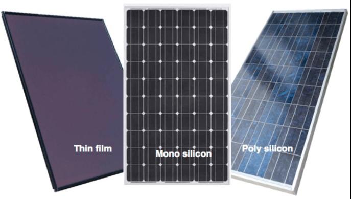
PV Modules convert sunlight directly into DC electricity. Solar cells (which are normally made of crystalline, polycrystalline or amorphous silicon or other compound semiconductors like Cadmium TellurideCdTe and Copper Indium Gallium Selenide-CIGS) are connected in series and encapsulated in a PV module. PV modules are rated for a particular power capacity at standard testing conditions (STC), which is also indicated on its label. In the market, different modules are used depending on cost and technical considerations. These are predominantly identified according to their cell type:
-
Monocrystalline
-
Polycrystalline
-
Thin-film (Amorphous, micro crystalline, CdTe or CIS Modules)
The specifications of a module are provided by the manufacturer on a nameplate given behind the module. The safety and quality of the PV module is ensured through appropriate certifications, warranties and guarantees. PV modules typically carry a performance warranty of 90 percent of the nominal power output for the first 10 years, and 80 percent for the next 15 years. The workmanship warranty on the PV module is typically for 5 years and covers against any defects in the material or construction of the PV module.
Strings and Arrays
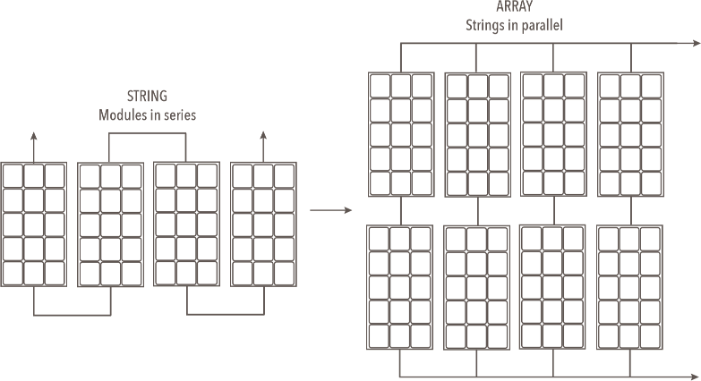
A number of PV modules connected in series is entitled a string. A string is designed such that it provides an output voltage in a range that is compatible with the solar inverter’s input voltage range. Strings are then connected in parallel in a PV plant to accomplish the desired DC capacity. The maximum allowable
string voltage in India is 1000 VDC. When a number of strings are connected in parallel, it forms an array. Module in a string (i.e. in series) adds up the voltage, and modules in an array (i.e. in parallel) add up the current.
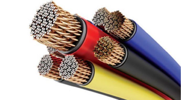
DC Cables
DC cables are used to carry DC current from the PV modules right up to the inverter. The DC cable should be sized to carry the required current (along with necessary safety margins) and also limit the voltage drop (i.e. resistance losses). Typically, single-core multistranded copper cables with cross section 4 or 6 mm2 rated for a maximum voltage of 1.8 kVDC are used for string connections of PV modules up to the string junction box. It is a common practice to use red-colored sheath for positive terminal of the string and black-colored sheath for negative terminal of the string. The DC cables used in solar strings use specialized connectors. As these connectors are usually installed outdoors, they should be IP67-rated, UV and fire-resistant with a typical operating temperature of - 40°C to +85°C. The contact resistance at the DC connectors should be minimal (typically less than 0.5 mΩ) rated for at least 30 ADC (but not less than the short-circuit current expected through that connector with necessary safety factors) and 1,000 VDC. DC Cables from string junction box (see below) to inverter are typically longer. They are sized to carry the required current and also limit the voltage drop. As a general practice, the DC wiring should not cause more than 2 percent power loss in the PV system.

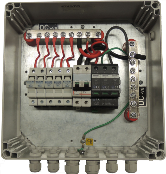
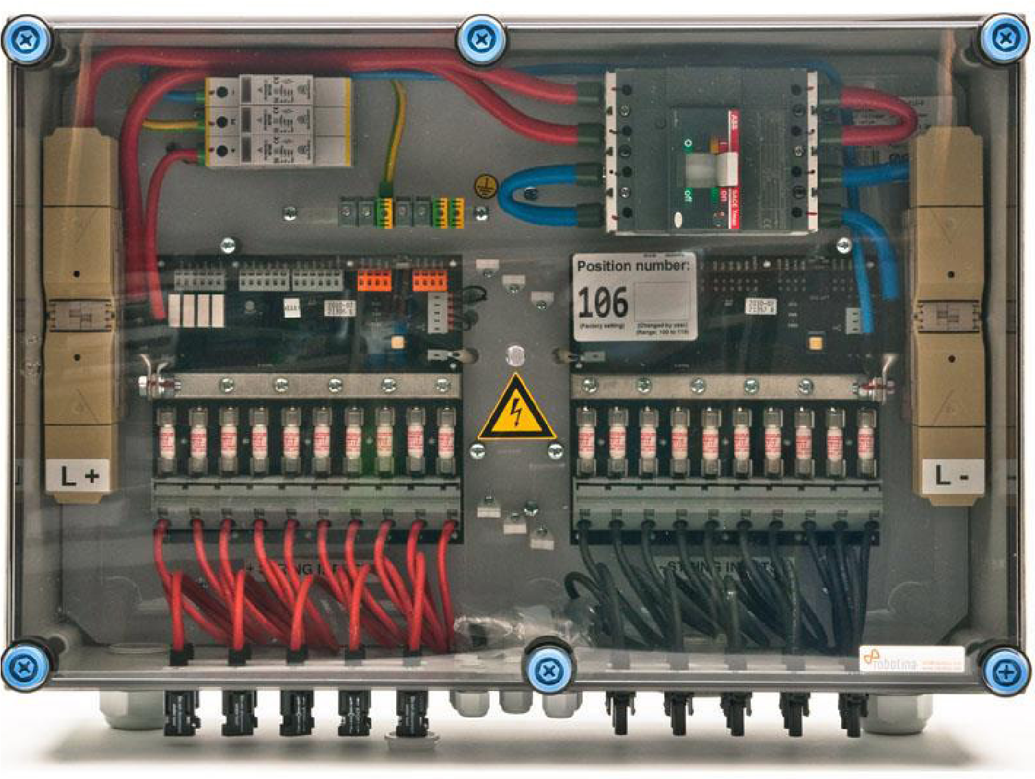
The String Junction Box (SJB)
The String Junction Box (SJB) combines several DC strings in parallel. SJBs are also known as String Combiner Box (SCB) or Array Junction Box (AJB) or PV Generator Junction Box. SJBs should be weather resistant as they are normally installed outdoors. SJBs should contain fuses and surge protection devices (SPD) to protect the PV modules as well as inverters. If the inverter has sufficient number of DC input terminals along with surge arrestor and overcurrent protection capabilities, then the SJB itself can be completely evaded in the PV system.
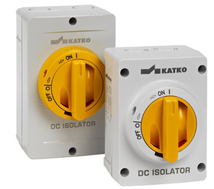
DC Isolators
DC Isolators are required to disconnect the PV modules and strings from the rest of the PV system in cases of faults, fire or repair. Most PV inverters already consist of a DC isolator, which should suffice. DC isolators are mandated globally; they should be clearly labeled and easily accessible.
Isolation Transformers(Optional)
Isolation Transformers are used to safeguard the inverters from grid-side surges as well as to avoid any DC injection from the inverter into the grid. Many inverter models also have in-built isolation transformers. However, isolation transformers increase the cost and also decrease the efficiency of the system. Inverters available in the market today without such transformers have adequate protective components and hence, such transformers are now discretionary. However, isolation transformers also serve
another purpose, which may be more relevant for certain grids or locations. If one regularly experiences lower voltages (especially at the tail ends of the grid) or higher voltages (especially near the substations), such voltages may not be a fault but still may cause the inverter to shut down. In such cases, an isolation transformer with a slight tap change to marginally increase or decrease the grid voltage for the inverter can be used. Isolation transformers are not required if the PV system is utilizing additional transformer such as a step-up transformer to step up the voltage to 11 kV. are used to safeguard the inverters from grid-side surges as well as to avoid any DC injection from the inverter into the grid. Many inverter models also have in-built isolation transformers.
However, isolation transformers increase the cost and also decrease the efficiency of the system. Inverters available in the market today without such transformers have adequate protective components and hence, such transformers are now discretionary. However, isolation transformers also serve another purpose, which may be more relevant for certain grids or locations. If one regularly experiences lower voltages (especially at the tail ends of the grid) or higher voltages (especially near the substations), such voltages may not be a fault but still may cause the inverter to shut down. In such cases, an isolation transformer with a slight tap change to marginally increase or decrease the grid voltage for the inverter can be used. Isolation transformers are not required if the PV system is utilizing additional transformer such as a step-up transformer to step up the voltage to 11 kV.
Inverters
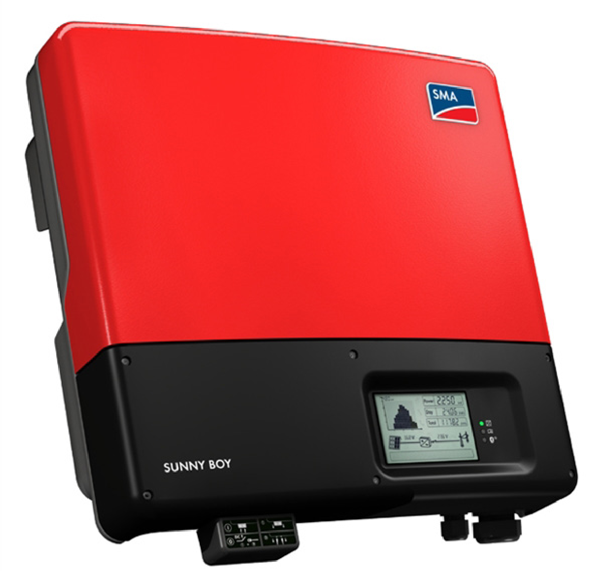
Inverters are among the most critical components of the PV system that not only perform power-related functions but are also responsible for the intelligence of the PV system. The major functions of the grid-connected PV inverter are to:
-
Extract maximum power from the PV modules (by optimizing the inverter’s input impedance);
-
Convert DC power into AC power;
-
Synchronize the output AC power with the phase, frequency, and voltage of the available grid in order to feed the PV power into the grid;
-
Ensure anti-islanding by shutting itself down (and hence the PV generation) in case of grid failure;
-
Ensure protection of the PV system from DC- side (i.e. PV-side) for reverse polarity, overcurrent, overvoltage and surge;
-
Ensure protection of the PV system from AC-side (i.e. grid-side) for grid-fault (e.g. over/ under-voltage, over/ under frequency, high rate of change of frequency, etc.), ground fault, residual current or fault conditions, etc.
Inverters should be rated for appropriate
Ingress Protection (IP). Single-phase string
inverters, typically
up to around 10 kW, give an output of 240 VAC, 1φ, 50 Hz; while three phase string inverters give an output of 415 VAC, 3φ, 50 Hz. It is also a general practice to use three numbers of single-phase inverters to provide a net three-phase output. For larger rooftop PV systems, central inverters of capacities more than 100 kW are often used, in this case the output voltage is stepped up to 11 kV or above using step-up transformers. PV inverters have generally 96-98 percent efficiency.
Solar Inverters are classified as below as per their application
-
Grid Connected Inverters
-
Stand Alone or Off Grid Inverters
-
Hybrid Inverters
Grid connected Solar Inverters are further classified as below as per their rated capacity
-
Central Inverter
-
String Inverter
-
Micro Inverter
-
Power Optimizer
AC Distribution Box (ACDB)
ACDB should be placed close to the inverter immediately after the inverter (or the isolation transformer, if used). The primary function of the ACDB is to isolate the PV system (including PV modules and inverters) from the grid. Additionally, the ACDB
should contain Miniature Circuit Breakers to disconnect incoming and outgoing AC connections, Residual Current Circuit Breakers (RCCB) and SPD. [Note: RCCB and/ or SPD may not be required if the inverter has these components.]
AC Cables
AC Cables carry the AC power of the PV system to the metering point, which is typically at the lower floors and hence has to be carefully chosen to ensure safety as well as to minimize power loss. While copper or aluminum cables can be used, it is highly recommended to use armored cables. AC cabling practices are common in India and suitable standards and certifications should be adhered to. As a common practice, AC wiring loss of a PV system should not exceed 2 percent.
Module Mounting Structures (MMS)
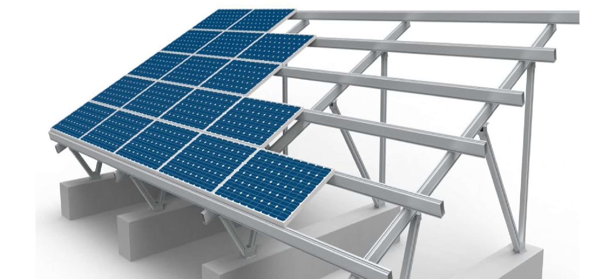
Module Mounting Structures (MMS) are used to secure the PV modules in particular orientation to collect maximum sunlight. MMS are designed keeping several structural considerations such as:
-
Load (weight) of the PV system Load bearing capacity of the terrace, rooftop or the structure on which the PV system is mounted;
-
Typical and maximum wind loads at that particular location, also factoring the height of the installation;
-
Seismic zone safety factors;
-
Other considerations such as saline or corrosive environments;
Most of the physical considerations are governed by Indian Standards. PV modules are often mounted at a tilt angle lower than the optimum angle for maximum energy generation. Lower tilt angles reduce the wind loads encountered by the PV system, resulting into a lighter MMS and also avoid the need to puncture a terrace, which may cause water seepage problems in the future. The mounting of PV modules should be optimized from a techno-commercial standpoint rather than just a technical performance standpoint.
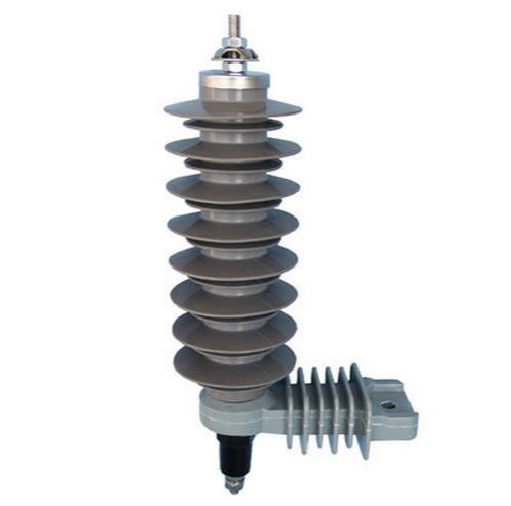
Lightning Arrestors
While it is desired to protect all PV systems from lightning, Lightning Arrestors may not be mandated for PV systems with capacities less than 10 kW. It is highly recommended for PV systems to have dedicated lightning arrestors rather than depending on foreign rods and structures at greater heights that might exist at the time of installation.
Earth Pits
Earth Pits used in solar PV systems are the same as conventional earth pits used for electrical installations and also follow the same standards. Each earthing system should have two earth pits, whether at the same end of the earthing system or each at the opposite end of the earthing system. This way, the risks from failure of the earthing system can be reduced and a lower earth resistance can be achieved.