BALANCE OF SYSTEMS
Inspection & Fault Identification
CABLES
Cables play a very important role in system designing and array layout configurations of a solar power plant. Cables should be planned in a way that they can last for 25 years. Cables are generally placed directly under the ground or in ducts of the underground distribution system. This is one of the reason, there being no major faults in the underground cables. However, if a fault does occur, it is difficult to locate and repair because these conductors are not visible. Following are the faults most likely to occur in underground cables:
-
Open-circuit fault
-
Short-circuit fault
-
Earth fault
Open-circuit fault
When there is a break in the conductor of a cable, it is termed as an open circuit fault. The open-circuit fault can be examined by using megger. For this, the conductors of the 3-core cable at the far end are shorted and earthe, then resistance between each conductor and earth is measured by using megger. If the conductor is not broken, the megger will indicate zero resistance in the circuit. However, if the conductor is broken, the megger will indicate infinite resistance in its circuit due to circuit break.
Short-circuit fault
When two conductors of a multi-core cable come in electrical contact with each other due to insulation failure, it is termed as a short-circuit fault. Here the two terminals of the megger are connected to any two conductors. If short circuit fault exists between conductors, the megger indicates a zero reading. The same should be repeated for other conductors by taking two of them at a time.
Earth fault
When the conductor of a cable comes in contact with earth, it is termed as an earth fault or ground fault. To identify this fault, one terminal of the megger is connected to the conductor and the other terminal is connected to the earth. If the conductor is earthed, the megger indicates a zero reading. A similar procedure should be repeated for other conductors of the cable.
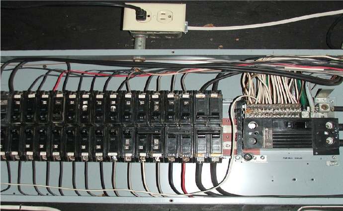
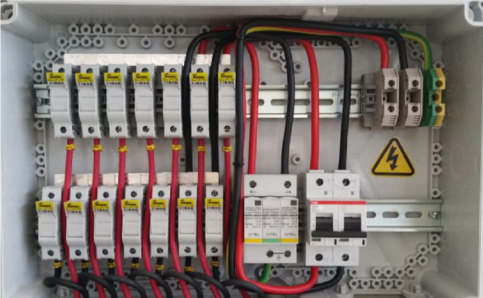
PROTECTION DEVICES
-
The requirements for overcurrent protection in PV systems can be complex. To know whether an overcurrent protection device is required or not is crucial for both safety and performance. In case of an emergency or other need to shutdown, such as maintenance, disconnect switches are used to easily open-circuit ungrounded, current-carrying conductors.
-
Disconnecting a piece of equipment means switching “OFF” the ungrounded conductor of circuit (creating an open circuit), thus stopping the flow of current and removing the voltage potential
-
Overcurrent protection devices (OCPDs) protect the conductors connected to them by preventing current levels in the circuit that exceeds the ampacity rating of the conductors.
-
Fuses and circuit breakers are examples of overcurrent devices; they are rated in amps and if the rating exceeds for a specific duration of time, the fuse will blow or the breaker will trip.
-
This opens the circuit and stops the flow of current before the conductor is damaged.
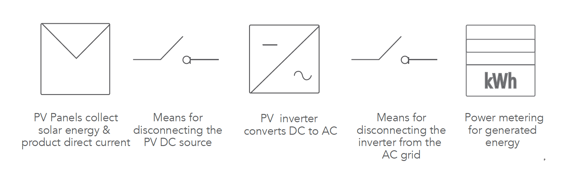
Block diagram of PV System indicating location of disconnects
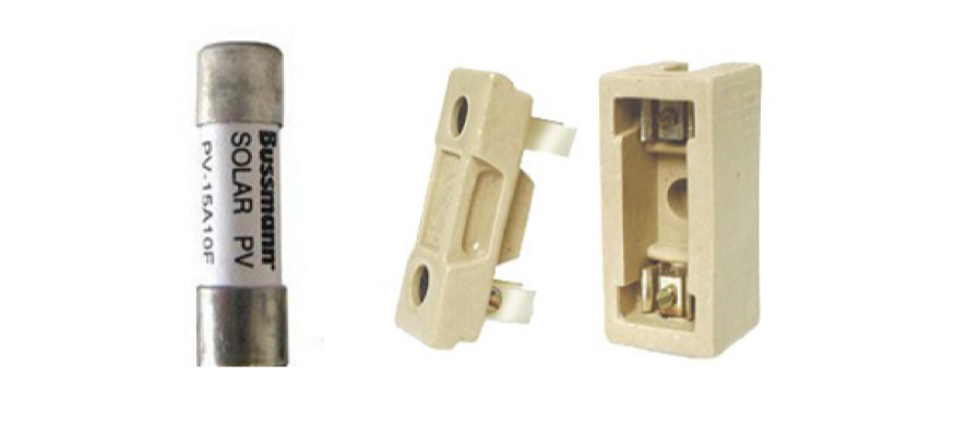
FUSE
One of the most essential aspects of electrical wiring of photovoltaic systems are fuses. Fuse provides integral safeguard against overcurrent that could otherwise damage your valuable PV equipment. It is a type of low resistance resistor that acts as a sacrificial device responsible for protection from over current.
“Fuse blow for a specific reason”, whenever a blown fuse is found, investigate the reason behind it. The essential component that will deteriorate in the fuse is a metal wire that melts when an excessive amount of current flows through it. Some common explanations for current fluctuations that result in blown fuses are:
-
Short circuit
-
System overload
-
Other device failures (modules etc.)
-
Lightning
-
Static electricity
A typical fuse will blow at an ambient temperature under the following conditions
|
%of amp
|
Time to Blow Fuse
|
| 110% |
4 hours minimum |
| 135% |
1 hour maximum |
| 200% |
5 minutes maximum |
-
When replacing fuses, it is essential to source the appropriate size, type, and rating. Do not assume that the fuse being replaced is the correct size, type, and rating, because an incorrect rating or size could be a reason for the fuse to blow.
-
It might be necessary to consult the product manual to confirm the correct fuse to be sourced.
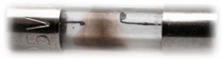
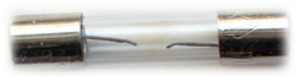
The small element cross-section melts quickly under short-circuit conditions. The effective heat transfer allows the fuse to carry harmless overloads. When a sustained overload occurs, the element will start generating heat at a faster rate, then the heat can be passed to the filler. If the overload persists, the element will start reaching its melting point and would open.
Effect of blown Fuse
Example
Consider a situation, where a fuse was burnt in the array junction box and the output of that string was zero since many days. The same should have been identified just by looking at the SCADA system. Although SCADA was showing zero output, but due to the small and overlapping values shown in the graphical user interface on the computer screen, it was nearly impossible for anyone to identify this problem. As a result, the output of the whole array was sacrificed for several days, which could be avoided, just by changing the blown out fuse.
Let us consider an example of the financial effect of a blown fuse on a 5 kW system.
|
Parameter
|
Specifications
|
| Plant Capacity |
5 kW |
| Max Power@STC |
250 Wp |
| Total No. of Modules |
20 modules |
| No. of strings |
4 |
| No. of modules in each string |
5 |
| Performance Ratio (PR) |
85% |
| Sunshine Hrs. |
5 Hrs. |
Assume fuse is blown in single string
| Daily generation 15.9 (Fuse Blown) |
21.25 (Fuse not Blown) |
| Units gained = (21.25 – 15.9) |
5.35 Units |
| Savings = (5.35 × 5.14** ) |
Rs. 27 / day |
| Monthly Saving = (Rs 27 × 30) |
Rs. 810 / month |
| Annual Saving = (810 × 12) |
~ Rs.9,720 /year
|
|
Financial analysis of blown fuse
Daily energy loss = No of modules (single string) × Watt peak rating of modules × PR × Sunshine hours. Daily generation = Total no of modules × Watt peak rating of modules × PR × Sunshine hours *Assumption: 85% PR. The performance ratio tells us how well a plant is engineered to generate electricity at a given module efficiency and a given irradiation level. **Assumption: Rs. 5.14/kWh is the power tariff rate of an average residential customer |
BATTERIES
The goal of battery care and maintenance is to improve the battery’s performance and life. Battery life is a highly variable property that depends on a host of factors such as storage temperature and depth of discharge (DOD).
The following needs to be observed during a battery inspection:
-
Terminal rusting generally is the main problem of all batteries. Rusting in terminals reduces the current flow to and from the battery. This considerably affects the life of battery and inverter efficiency. Maintenance free batteries also need care against rusting in terminals. Contacts affected by rust, restrict the charging current and slow down the rate of charging; this in-turn reduces the life of the battery which is irreversible.
-
Clean the battery terminals at least once in a month. About 80% of failures are caused by sulfation (a process where Sulphur crystals form on the battery’s lead plates and prevent chemical reactions from happening). When the battery has a low charge or electrolyte level then sulfation occurs. Thus, it is very important to monitor, maintain and control sulfation in flooded batteries. To do this you will need distilled water, digital voltmeter, temperature compensating hydrometer and proper safety gear.
Maintenance & Troubleshooting
BASIC LEVEL
Cables
Many plant outages occur due to cable breakdowns. Problems arises in cables largely due to the following reasons:
-
Optimizing sizing
-
Cable routing
-
Voltage drop Figure 100
The following checks must be performed during inspection & maintenance
Check for cable routing
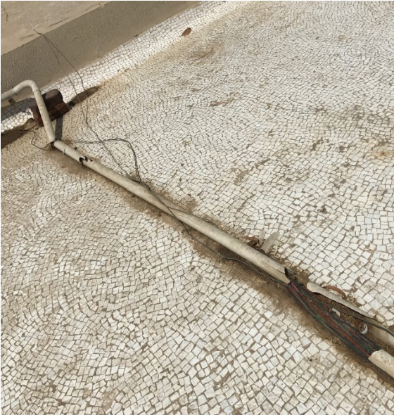
The cables shall be routed properly and fastened with clamps to avoid any damage to the cables. If the cables are not properly routed and the wires are left hanging, this may cause damage to cables because of rodents, squirrels and other pests or can cause hazard when people walk around the terrace.
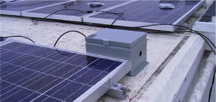
Incorrect cable routing
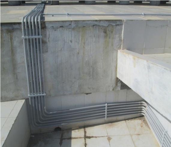
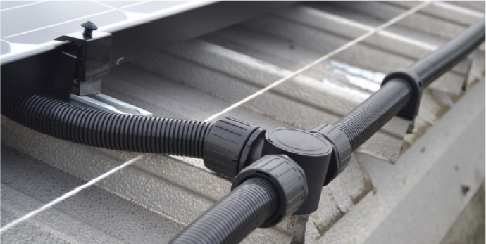
Proper cable routing
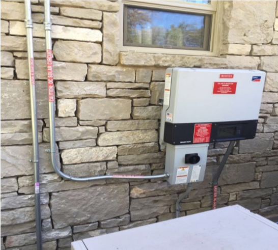
Proper cable routing
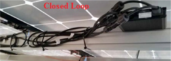
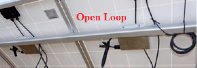
Closed Loops & Open Loops
Many times we notice that cables are not properly looped. Sometimes the cable loops are very tight or very loose. Loose connection may lead to a fire hazard and tight connections may lead to breakage of the cable. Wiring of the loops should be of proper diameter.
-
Check that all cable connections are tightened and securely fastened.
-
Check that all cables are properly insulated, without insulation damage. Check for quality of outer sheath and conductor insulation.
-
Check whether separate single core cables have been used for the positive and negative conductors of DC circuits.
-
Check whether unused cable entries have been closed. All unused cable and conduit openings shall be plugged with blind plugs or caps to prevent entry of dust, insects, squirrels, rats and other pests.
-
Check for the quality of conduits (diameter, wall thickness)
-
Electrical rooms, niches, switch boards and distribution boards should be kept clean and neat. The immediate surroundings of all electrical systems should be kept clean and free to allow access at any time.
-
Check for proper labeling of cables
-
PV modules cables are generally tied by a ‘cable tie’. Check that they are tied properly and not loosely mounted.
-
The MCB’s, isolators, connectors, switches, fuses and other components should be of ratings that match the cables, wires and equipment to be protected by these components.
-
Check for all cables and wires should be of adequate current rating.
-
The MCB’s, isolators, connectors, switches, fuses and other components should be of ratings that match the cables, wires and equipment to be protected by these components.
-
Check for all cables and wires should be of adequate current rating.
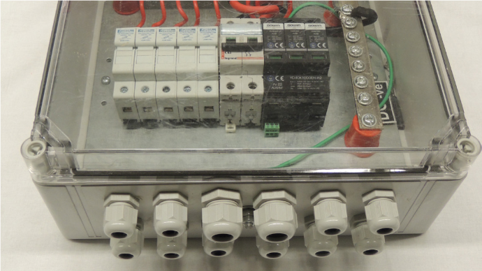
 Correct cabling connection
Incorrect – Cable conduit are not closed
Correct- Cable conduit are closed
Incorrect - Conduits are damaged
Correct - Conduits are in proper condition
Cables are not labelled properly
Cables are labelled properly
It is observed that a very common mistake is to use a fuse that is rated for 1000 VAC on a DC disconnect that is rated for 1000 VDC. At first sight, the cable size and the current rating may seem correct, however, the voltage rating (a small description on the fuse is even more important than the current rating in some circumstances. Unless DC application ratings are provided by the fuse manufacturer the AC rated fuses SHOULD NOT be used in DC voltage circuits.
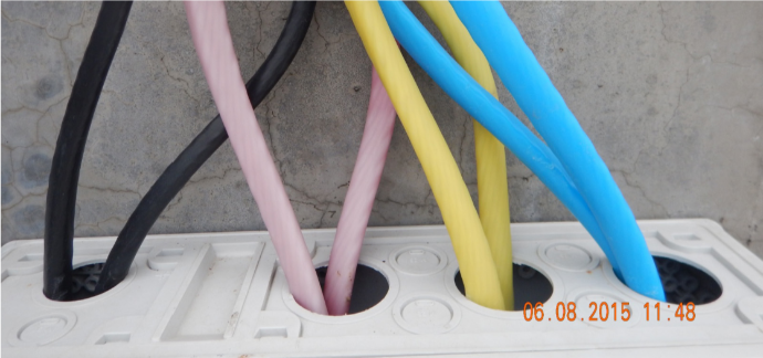
Colour coding of wires and cable conductors shall be strictly followed as per article 3.6 of the National Electrical Code.
| System |
Item |
Color |
| Supply AC system |
Phase 1 L1 Phase 2 L2 Phase 3 L3 Neutral N |
Red
Yellow Blue Black |
| Apparatus AC system |
Phase 1 U Phase 2 V Phase 3 W Neutral N |
Red Yellow Blue Black |
| Supply DC system |
Positive L+ Negative L- Mid wire M |
Red
Blue Black |
| Supply DC system (single phase) |
Phase L Neutral N |
Red
Black |
| Protective conductor |
PE |
Green and Yellow |
| Earth |
E |
No color other than the color of the bare
conductor. If insulated, the color for insulation
should be chosen to avoid those listed above
for designation of other conductors |
Mounting Structures
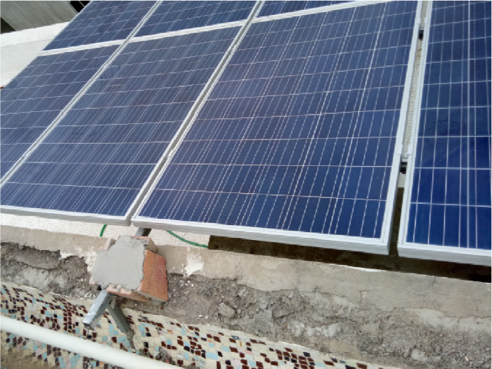 Bad Installation
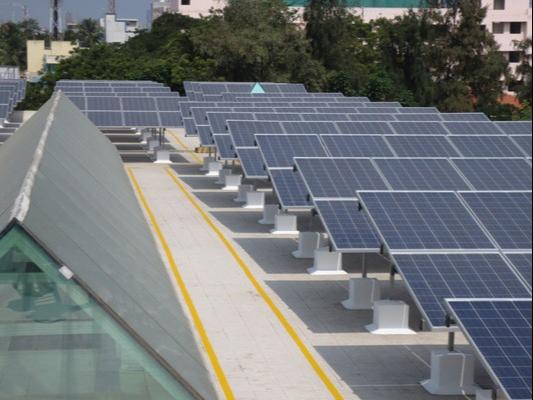
Good Installation
-
Visual inspection of each component as per plans - the model number, Standards etc.
-
For the Rooftop systems the mounting must be secure and weather tight
-
If it is a roof mounted system, ensure that the roofs are capable of handling additional weight of PV system
-
Proper ventilation, must be provided behind array to prevent overheating
-
Cable entry must be weather proof
-
Ground the system parts correctly in order to reduce the threat of shock, hazard and induced surges
-
Aluminum should not be placed in direct contact with concrete
-
Ensure the design meets the local utility interconnection requirements
-
Check mounting structures for rusting and corrosion.
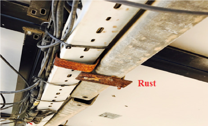
Rusting of Mounting structure
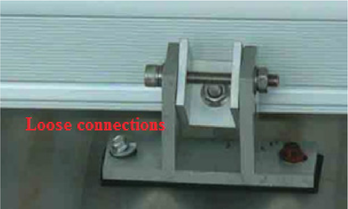
Loosed clamps
-
Array frame must be correctly fixed and the material used should corrosion free
-
Check if all the clamps are properly tightened.
-
Check the distance between rows of Solar PV modules (passage for cleaning and maintenance).
-
Check the tilting angle. The optimal tilt of the fixed PV module is approximately the degree of latitude of that location (facing South in India). However, it is an acceptable practice to install the PV modules at lower tilt angles (in the range of 10° to 15°) on flat roofs/ terraces for the following reasons:
-
PV modules installed at lower tilt angles encounter lesser wind (and hence, uplift) forces. Hence, the PV modules and their mounting structures can often be installed safely on the flat roof/ terrace by simply adding more weight (like bricks) and using wind blockers rather than using bolts to puncture/ penetrate the terrace to anchor the PV system.
-
PV modules installed at lower tilt angles cast shorter shadows, thus allowing lower inter-row spacing between the PV modules. Hence, a higher capacity (in kW) can be installed in a given roof/ terrace area.
-
Mounting structures for PV modules at lower tilt angles are lighter, and thus, reduce the cost of the overall PV system.
-
Mounting structures for PV modules at lower tilt angles are simpler, thus they reduce the time for installation (and hence, also reduce the cost).
-
NOTE:
If a customer notices that a nearby building which has the same plant capacity but different
tilt angle, it should be noted that with the difference in tilt angle, output varies.
Protection Devices
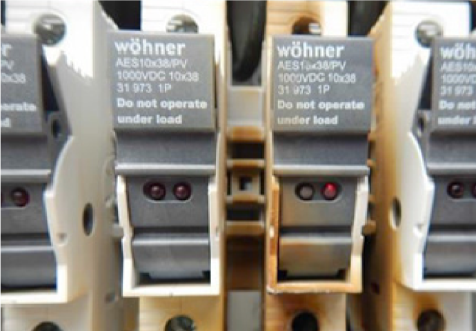
Fuses - Burnt out
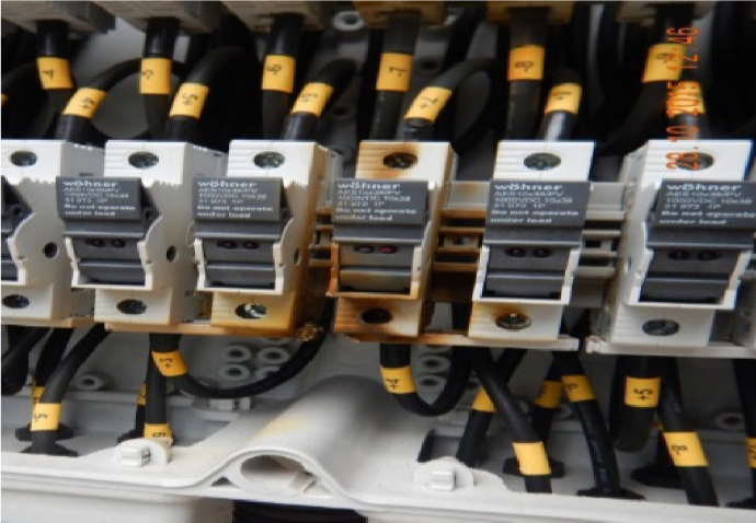
Fuses - Burnt out
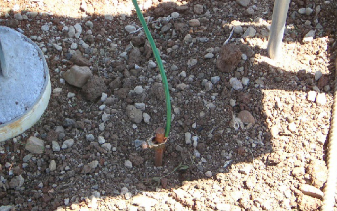
Grounding
-
Visually inspect the fuses
-
Large surges can immediately destroy equipment and can also melt conductors. Typical location for surge protection are at the ac output and dc input of inverter, and dc combiner boxes. The best surge protection is a well grounded system. SPD’s are connected in parallel with the circuit that is being protected so when the device fails, the circuit will be energized but will no longer be protected from surges.
The reasons for grounding include the following:
-
To prevent voltage potentials and current on conductive surfaces where it could cause an electric shock, start fire or cause death.
-
It provides a path for fault-current flow, helping to ensure the proper operation of overcurrent devices such as circuit breakers and fuses.
-
To limit spikes and surges from lightning or other high-voltage conditions.
-
To stabilize voltage and provide a common reference point (the earth).
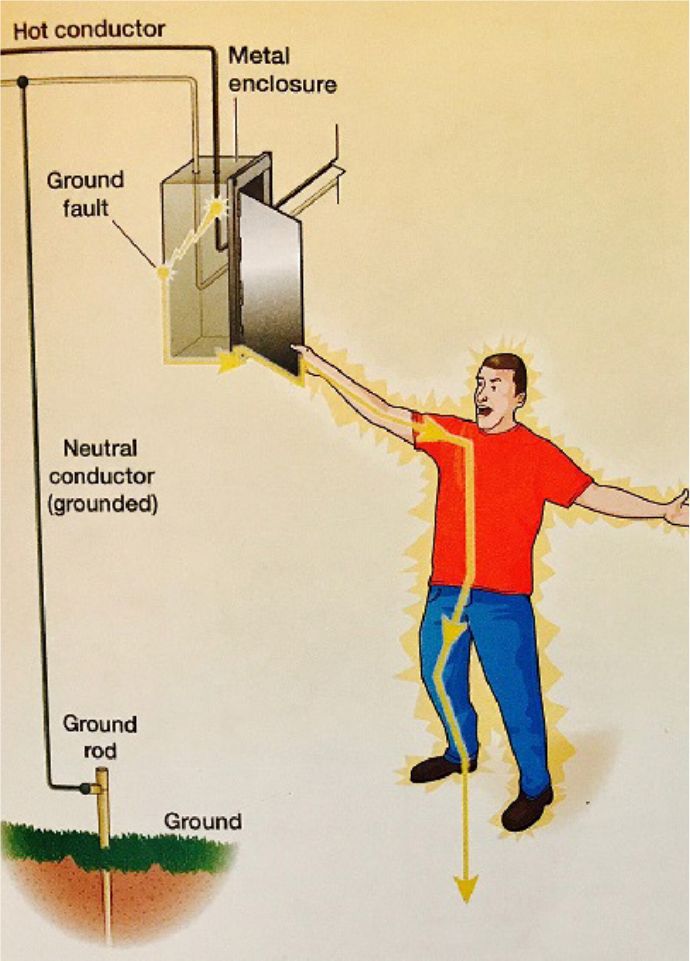
No Equipment Grounding
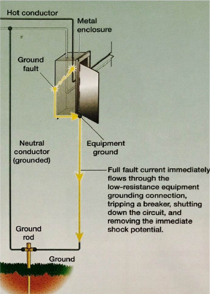
Proper Equipment Grounding
-
The above figure on the left shows a person getting an electric shock due to improperly grounded metal enclosure. In this illustration the ground fault has occurred. So when the person unwittingly touches it, current flows through their entire body to ground causing shock or death. The figure on the right shows a properly grounded system, with the metal enclosure connected to the ground rod by the equipment grounding conductor.
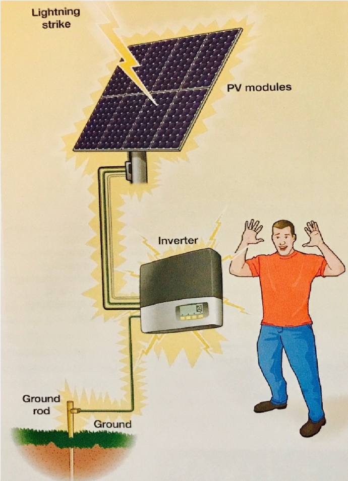
Poor Lightning Protection
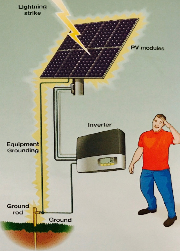
Good Lightning Protection
-
The above figure on the left shows the poor grounding that increases the risk of damage from lightning strikes. In this scenario, the only path for lightning is through the wiring from the array to the inverter and then on to ground. This can likely damage the inverter. The figure on the right shows better lightning protection with an additional array grounding electrode conductor connected directly from the PV modules to a ground rod. With this lightning arrangement, the risk of lightning damage is greatly reduced.
Monitoring of Rooftop PV System
It is useful to install a monitoring and data logging device for a solar PV system. Many solar grid inverters have a built-in monitoring system that can be connected to internet for the purpose of remote monitoring. There are also third party system monitoring and data logging devices available. A PV system can be monitored at various levels based on the capacity of the PV system and type of involvement of the stakeholder generally as follows:
At PV module-level
This is done using either micro-inverters
or DC-DC converters/ optimizers at each
module, where monitoring is provided as an
added functionality.
However, such micro-inverters/ converters/
optimizers increase the capital cost of the PV
system, and hence, are not popularly used.
At string-level
This is done mainly using current sensors to each string in the string junction boxes which are connected to a supervisory control and data acquisition (SCADA) system. In string monitoring systems, the electrical output of each PV string is compared with each other and also as a function of the ambient weather parameters.
Hence, any under-performing string can easily be identified and the under performance can be detected only to a few PV modules. However, the cost of such systems are justified in bigger PV plants.
Typical parameters that are monitored and logged are:
-
Day solar energy produced (kWh)
-
Cumulative solar energy produced(kWh)
-
Maximum DC voltage (V)
-
Maximum DC current (A)
-
Cumulative hours of operation (h)
-
Maximum AC voltage (V)
-
Maximum AC current (A)
-
Maximum AC frequency (Hz)
-
Minimum AC frequency (Hz)
-
Errors
Figure below shows the SCADA image sample showing the energy generation of 5 kW installed capacity of the Rooftop PV System
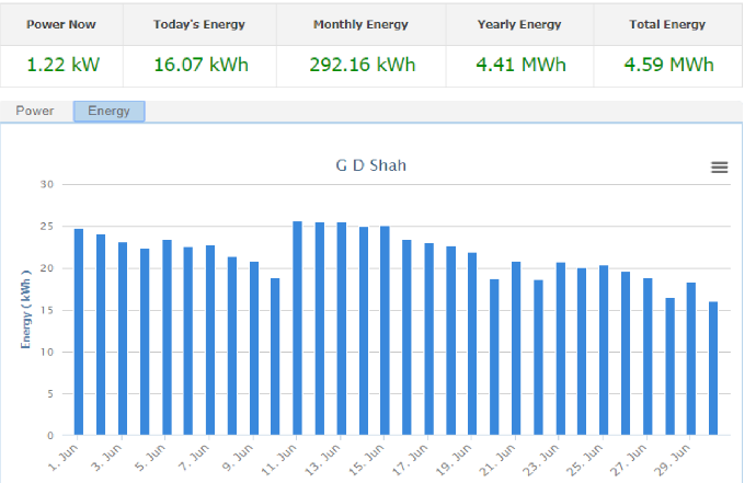
SCADA: Displaying the daily energy generation of PV System
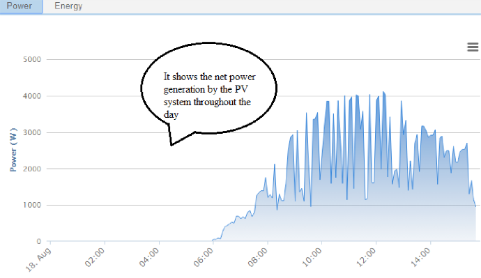
SCADA: Displaying the daily power generation of PV System
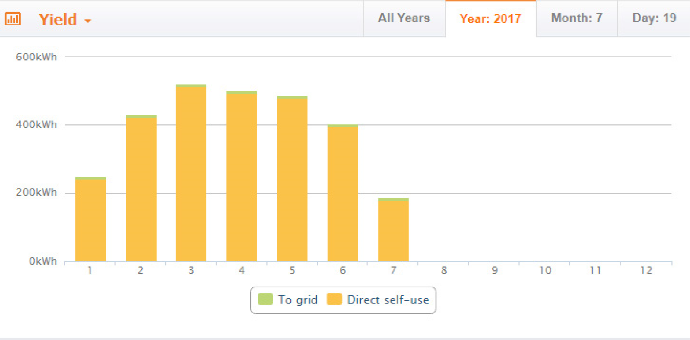
SCADA: Displaying units consumed for self-use and exported to grid
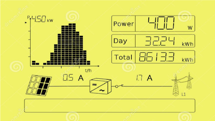
Inverter display screen showing units generated by PV system
Most PV inverters come with a monitoring functionality indicating critical parameters such as instantaneous currents and voltages, input DC and output AC power, energy generated during the day or during a given timeframe, etc. In addition, most inverters also allow connectivity to their proprietary or third-party weather monitoring equipment. The display panel of the solar grid inverter may also show the cumulative energy production. But if the inverter becomes defective or is replaced by the manufacturer with a new inverter, the energy generation data is lost. Hence it is recommended to install a solar energy generation meter. The data of the inverter can be either read from their display or can be extracted by connecting USB or RJ45 cables, or wirelessly using Wi-Fi, radio frequency (RF) or Bluetooth. Inverters may also be monitored remotely using proprietary or third-party equipment using GSM/ GPRS or even locally available Wi-Fi.
At Meter-level
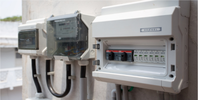
Net metering display screen showing units consumed by consumer
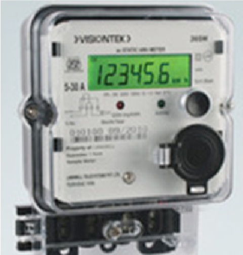
Meter-level monitoring of a rooftop or any other PV is the most critical for Utilities as well as Investors, as the energy meter is directly linked to each Stakeholder’s revenue. Meter-level monitoring can be done either entirely manually by the meter reader once during a billing cycle; or at another extreme, on a real-time-basis using remote wired or wireless communication.
ADVANCED LEVEL
Cable testing methods & techniques
PREPARATORY STEPS
-
All power supply and working circuits should be disconnected from the cable at both ends.
-
Meggering should be carried out when conductors and insulated parts like terminal blocks are clean and dry.
-
Before beginning and after the end of Meggering the cable conductors should be shorted/ earthed temporarily to discharge the accumulated charge.
Procedure of Cable Meggering
Following tests are performed for Meggering of Signaling cable:
Continuity Test
Tools and Instruments required:
-
Multimeter
-
Wire nipper
-
Box spanner
-
Screw driver
The continuity of cables is checked using a megger test. This test is conducted to confirm whether the core under test is electrically connected or showing break between both ends and to test the continuity and insulation of the cable conductors. For maintenance purpose of cables, the test should be carried out periodically (every year). The Meggering should be carried out at initial stages, before and after placing cable. Low insulation of cable leads to unintentional energization or de-energization of circuits. This test is carried out to check that the core under test is either showing break between both ends or continuous.
Testing can be commenced as per the following procedure:
-
Set the knob of Multimeter at Location A to check resistance at 200-ohm range.
-
Connect one probe of Multimeter to earth and other probe to the end of the cable conductor to be tested, as shown in figure below.
-
Instruct staff at the Location B, other end to connect earth to same conductor of the cable.
-
If earth is light at both ends, connect earth to armor also at both the ends.
-
The deflection of Multimeter needle indicates that the conductor under test is OK; otherwise there is a break in the conductor.
-
Then test the continuity of all other conductors with respect to this tested conductor. For example, to test conductor 2, connect the one probe of the Multimeter to conductor 2 and other probe to the tested conductor (at Location A). Instruct the staff at other end (at Location B) to short conductor 2 with the tested conductor.
-
Test continuity of all other conductors as above.