Types of solar rooftop
This section describes the common types of RTPV systems and the components that are necessary. This section is primarily aimed at the homeowner in order to get a better idea about the RTPV system. It gives an overview and highlights the importance of each component in the system.
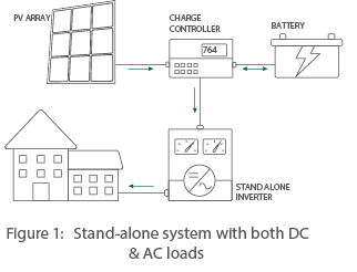
Stand Alone PV Systems (for places with no grid electricity)
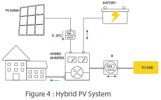
Stand-alone PV systems, which are isolated from the distribution grid usually, use stand alone inverters with batteries. The figure 1
shows a stand-alone system with both DC and AC loads and figure 2 shows a stand-alone system with only DC loads.
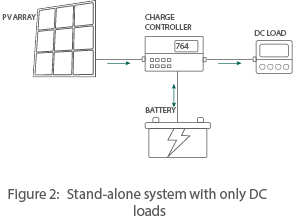
Gird Connected PV Systems(grid present, no or not many power cuts)
Grid-connected PV systems (also known as grid-tied systems), which are directly connected to the distribution grid, use grid connected inverters, and usually do not use batteries. These systems are capable of exporting surplus power into the distribution grid. A grid-connected PV systems is designed to automatically shut down if it detects anomalies in grid parameters such as voltage, frequency, rate of change of frequency, etc.
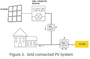
Hybrid PV Systems (grid present, but several power cuts)
Hybrid PV systems are connected to the grid and also have a battery backup. If a hybrid PV system observes anomalies in grid parameters, it is designed to isolate the consumer from the grid and continue to supply power from the PV system and batteries. The batteries can be charged by the grid or by solar energy in such systems.
System Components
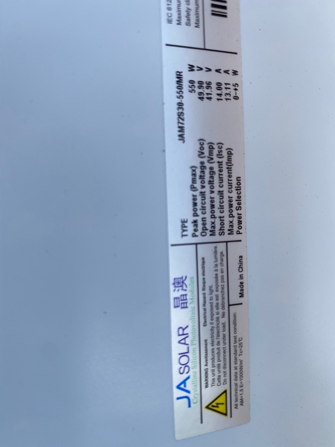
PV Modules
PV Modules convert sunlight directly into DC electricity. Solar cells (which are normally made of crystalline, polycrystalline or amorphous silicon or other compound semiconductors like Cadmium TellurideCdTe and Copper Indium Gallium Selenide-CIGS) are connected in series and encapsulated in a PV module. PV modules are rated for a particular power capacity at standard testing conditions (STC), which is also indicated on its label. In the market, different modules are used depending on cost and technical considerations. These are predominantly identified according to their cell type:
-
Monocrystalline
-
Polycrystalline
-
Thin-film (Amorphous, micro crystalline, CdTe or CIS Modules)
The specifications of a module are provided by the manufacturer on a nameplate given behind the module. The safety and quality of the PV module is ensured through appropriate certifications, warranties and guarantees. PV modules typically carry a performance warranty of 90 percent of the nominal power output for the first 10 years, and 80 percent for the next 15 years. The workmanship warranty on the PV module is typically for 5 years and covers against any defects in the material or construction of the PV module.
Strings and Arrays
-
A number of PV modules connected in series is entitled a string. A string is designed such that it provides an output voltage in a range that is compatible with the solar inverter’s input voltage range. Strings are then connected in parallel in a PV plant to accomplish the desired DC capacity. The maximum allowable string voltage in India is 1000 VDC. When a number of strings are connected in parallel, it forms an array. Module in a string (i.e. in series) adds up the voltage, and modules in an array (i.e. in parallel) add up the current.
DC Cables
DC cables are used to carry DC current from the PV modules right up to the inverter. The DC cable should be sized to carry the required current (along with necessary safety margins) and also limit the voltage drop (i.e. resistance losses). Typically, single-core multistranded copper cables with cross section 4 or 6 mm2 rated for a maximum voltage of 1.8 kVDC are used for string connections of PV modules up to the string junction box. It is a common practice to use red-colored sheath for positive terminal of the string and black-colored sheath for negative terminal of the string. The DC cables used in solar strings use specialized connectors. As these connectors are usually installed outdoors, they should be IP67-rated, UV and fire-resistant with a typical operating temperature of - 40°C to +85°C. The contact resistance at the DC connectors should be minimal (typically less than 0.5 mΩ) rated for at least 30 ADC (but not less than the short-circuit current expected through that connector with necessary safety factors) and 1,000 VDC. DC Cables from string junction box (see below) to inverter are typically longer. They are sized to carry the required current and also limit the voltage drop. As a general practice, the DC wiring should not cause more than 2 percent power loss in the PV system.
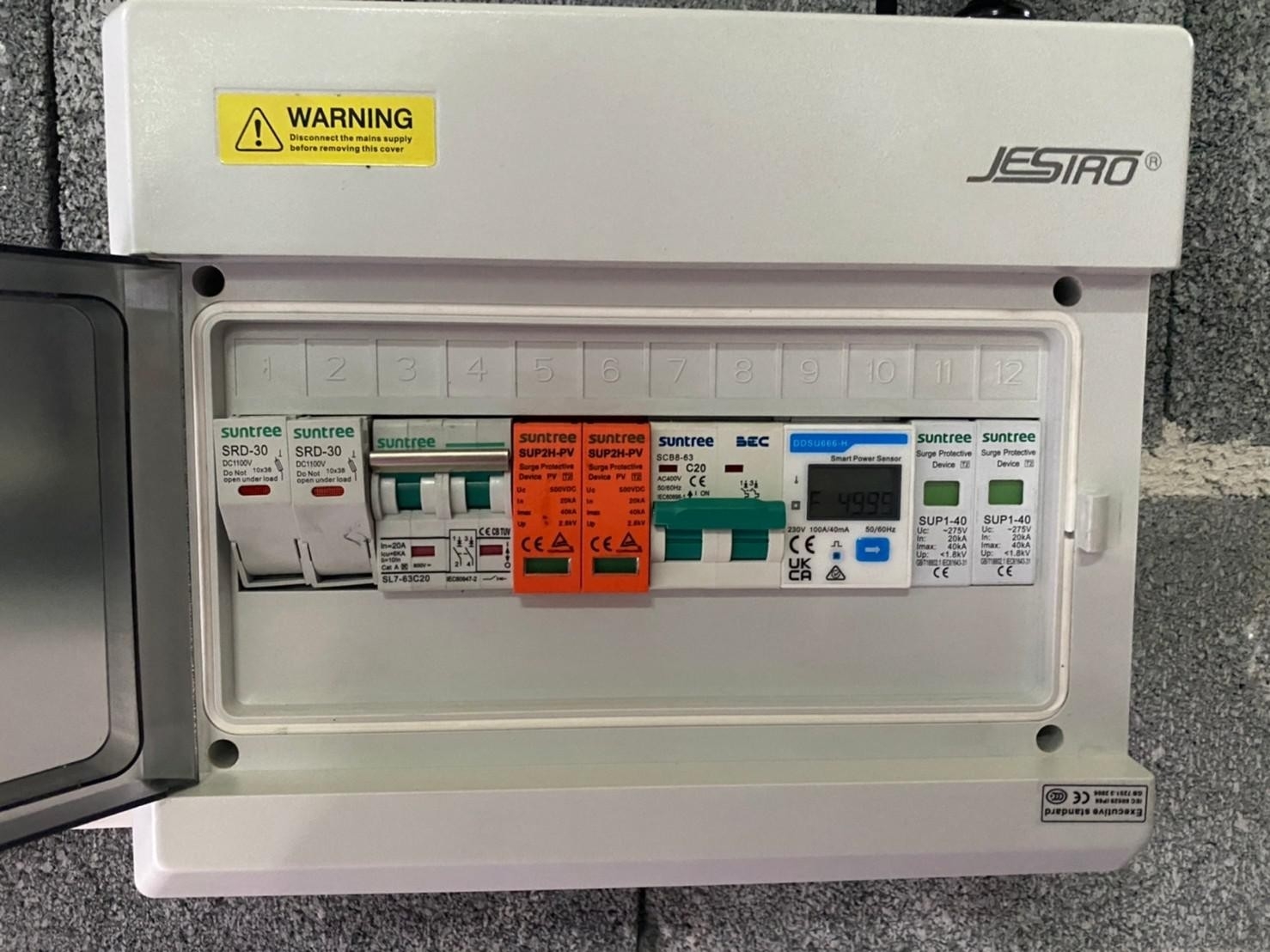
String junction box (SJB)
The String Junction Box (SJB) combines several DC strings in parallel. SJBs are also known as String Combiner Box (SCB) or Array Junction Box (AJB) or PV Generator Junction Box. SJBs should be weather resistant as they are normally installed outdoors. SJBs should contain fuses and surge protection devices (SPD) to protect the PV modules as well as inverters. If the inverter has sufficient number of DC input terminals along with surge arrestor and overcurrent protection capabilities, then the SJB itself can be completely evaded in the PV system.
DC Isolators
DC Isolators are required to disconnect the PV modules and strings from the rest of the PV system in cases of faults, fire or repair. Most PV inverters already consist of a DC isolator, which should suffice. DC isolators are mandated globally; they should be clearly labeled and easily accessible.
Isolation Transformers ( Optional)
Isolation Transformers are used to safeguard the inverters from grid-side surges as well as to avoid any DC injection from the inverter into the grid. Many inverter models also have in-built isolation transformers. However, isolation transformers increase the cost and also decrease the efficiency of the system. Inverters available in the market today without such transformers have adequate protective components and hence, such transformers are now discretionary. However, isolation transformers also serve another purpose, which may be more relevant for certain grids or locations. If one regularly experiences lower voltages (especially at the tail ends of the grid) or higher voltages (especially near the substations), such voltages may not be a fault but still may cause the inverter to shut down. In such cases, an isolation transformer with a slight tap change to marginally increase or decrease the grid voltage for the inverter can be used. Isolation transformers are not required if the PV system is utilizing additional transformer such as a step-up transformer to step up the voltage to 11 kV. are used to safeguard the inverters from grid-side surges as well as to avoid any DC injection from the inverter into the grid. Many inverter models also have in-built isolation transformers. However, isolation transformers increase the cost and also decrease the efficiency of the system. Inverters available in the market today without such transformers have adequate protective components and hence, such transformers are now discretionary. However, isolation transformers also serve another purpose, which may be more relevant for certain grids or locations. If one regularly experiences lower voltages (especially at the tail ends of the grid) or higher voltages (especially near the substations), such voltages may not be a fault but still may cause the inverter to shut down. In such cases, an isolation transformer with a slight tap change to marginally increase or decrease the grid voltage for the inverter can be used. Isolation transformers are not required if the PV system is utilizing additional transformer such as a step-up transformer to step up the voltage to 11 kV.
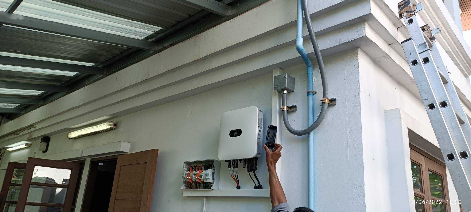
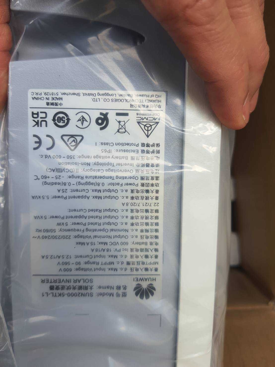
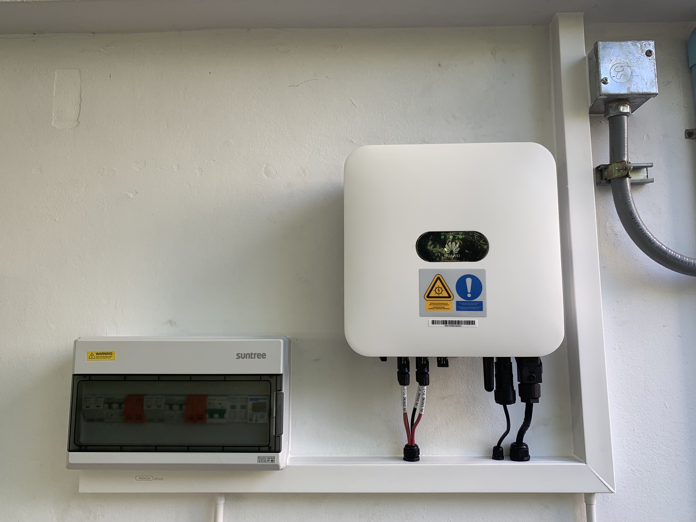
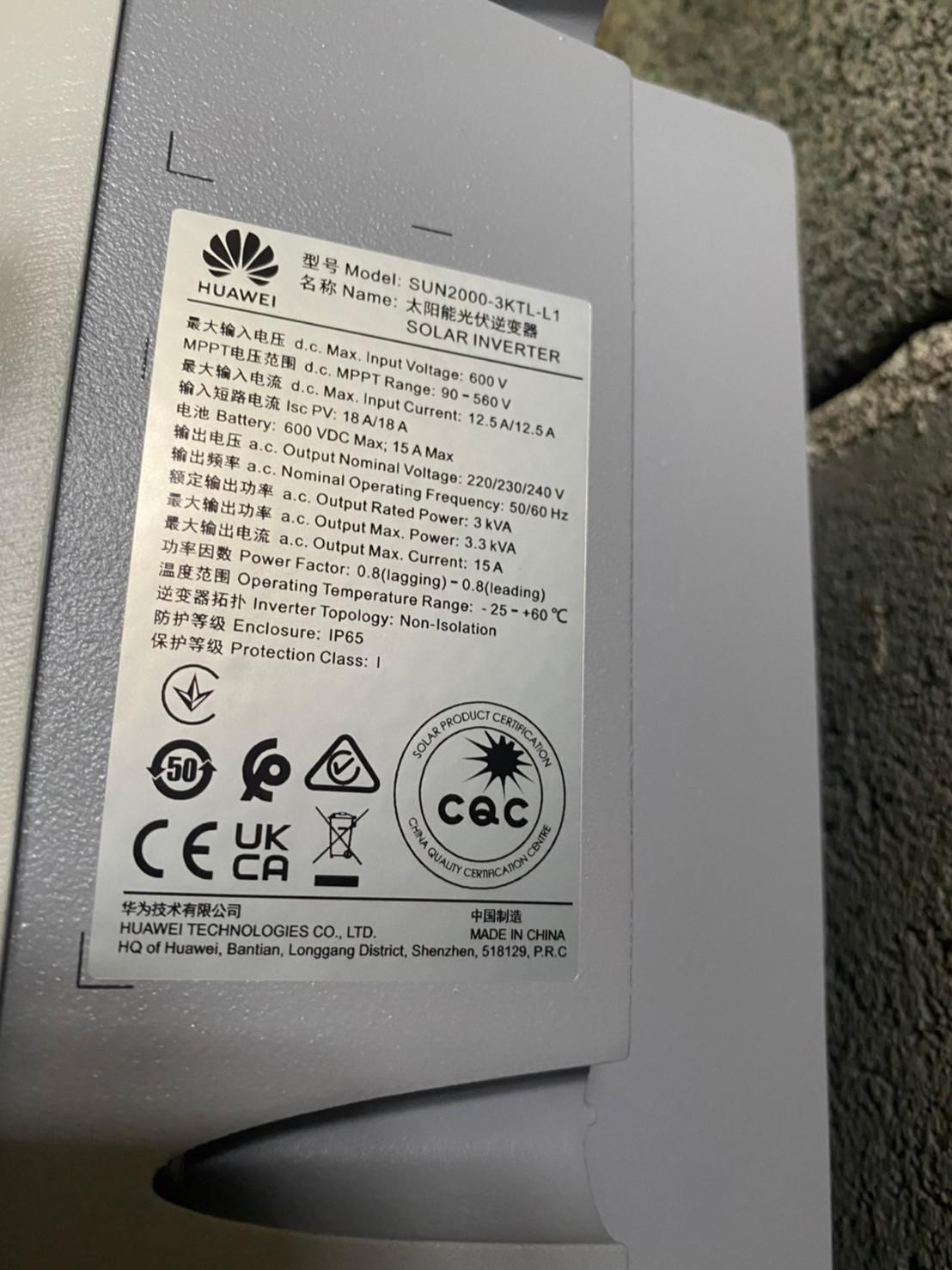
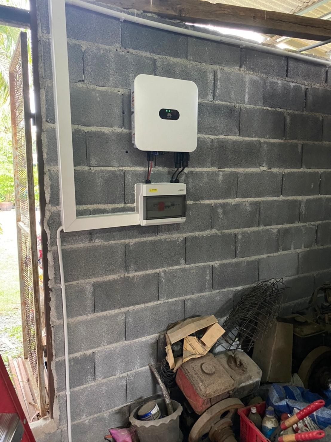
Invertors
Inverters are among the most critical components of the PV system that not only perform power-related functions but are also responsible for the intelligence of the PV system. The major functions of the grid-connected PV inverter are to:
-
Extract maximum power from the PV modules (by optimizing the inverter’s input impedance);
-
Convert DC power into AC power;
-
Synchronize the output AC power with the phase, frequency, and voltage of the available grid in order to feed the PV power into the grid;
-
Ensure anti-islanding by shutting itself down (and hence the PV generation) in case of grid failure;
-
Ensure protection of the PV system from DC- side (i.e. PV-side) for reverse polarity, overcurrent, overvoltage and surge;
-
Ensure protection of the PV system from AC-side (i.e. grid-side) for grid-fault (e.g. over/ under-voltage, over/ under frequency, high rate of change of frequency, etc.), ground fault, residual current or fault conditions, etc.
Inverters should be rated for appropriate Ingress Protection (IP). Single-phase string inverters, typically up to around 10 kW, give an output of 240 VAC, 1φ, 50 Hz; while three phase string inverters give an output of 415 VAC, 3φ, 50 Hz. It is also a general practice to use three numbers of single-phase inverters to provide a net three-phase output. For larger rooftop PV systems, central inverters of capacities more than 100 kW are often used, in this case the output voltage is stepped up to 11 kV or above using step-up transformers. PV inverters have generally 96-98 percent efficiency.
Solar Inverters are classified as below as per their application
-
Grid Connected Inverters
-
Stand Alone or Off Grid Inverters
-
Hybrid Inverters
Grid connected Solar Inverters are further classified as below as per their rated capacity
-
Central Inverter
-
String Inverter
-
Micro Inverter
-
Power Optimizer
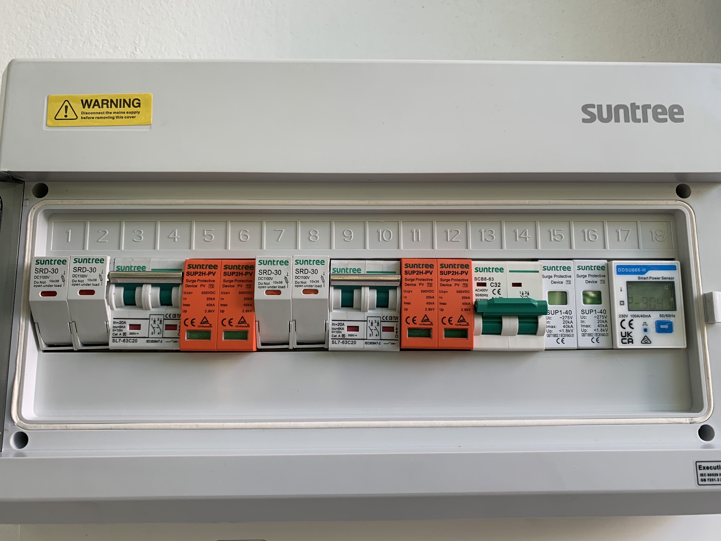
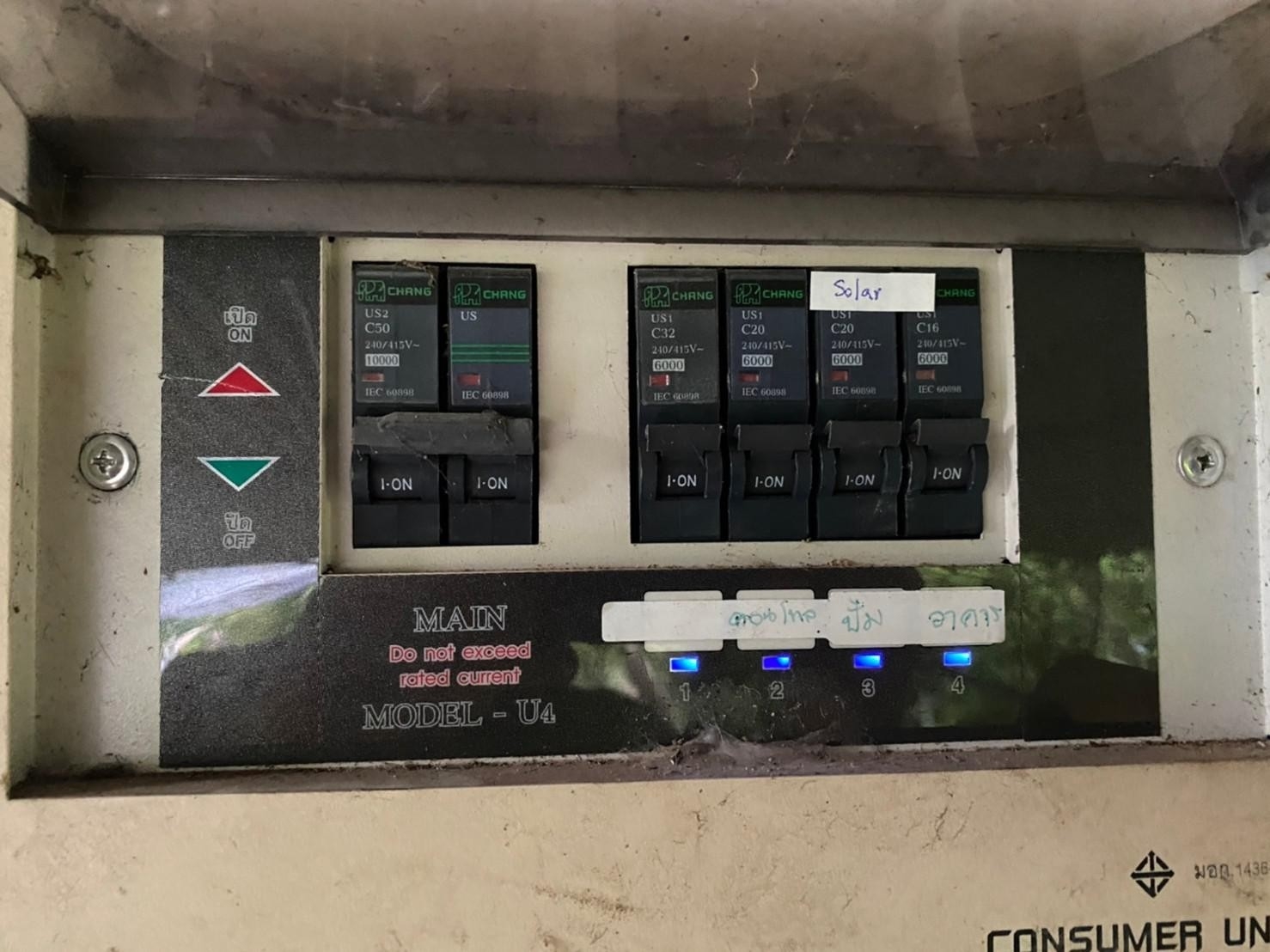
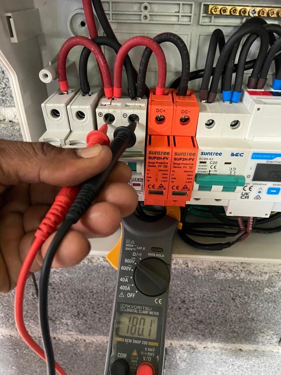
AC Distribution box (ACDB)
ACDB should be placed close to the inverter immediately after the inverter (or the isolation transformer, if used). The primary function of the ACDB is to isolate the PV system (including PV modules and inverters) from the grid. Additionally, the ACDB should contain Miniature Circuit Breakers to disconnect incoming and outgoing AC connections, Residual Current Circuit Breakers (RCCB) and SPD. [Note: RCCB and/ or SPD may not be required if the inverter has these components.]
AC Cables
AC Cables carry the AC power of the PV system to the metering point, which is typically at the lower floors and hence has to be carefully chosen to ensure safety as well as to minimize power loss. While copper or aluminum cables can be used, it is highly recommended to use armored cables. AC cabling practices are common in India and suitable standards and certifications should be adhered to. As a common practice, AC wiring loss of a PV system should not exceed 2 percent.
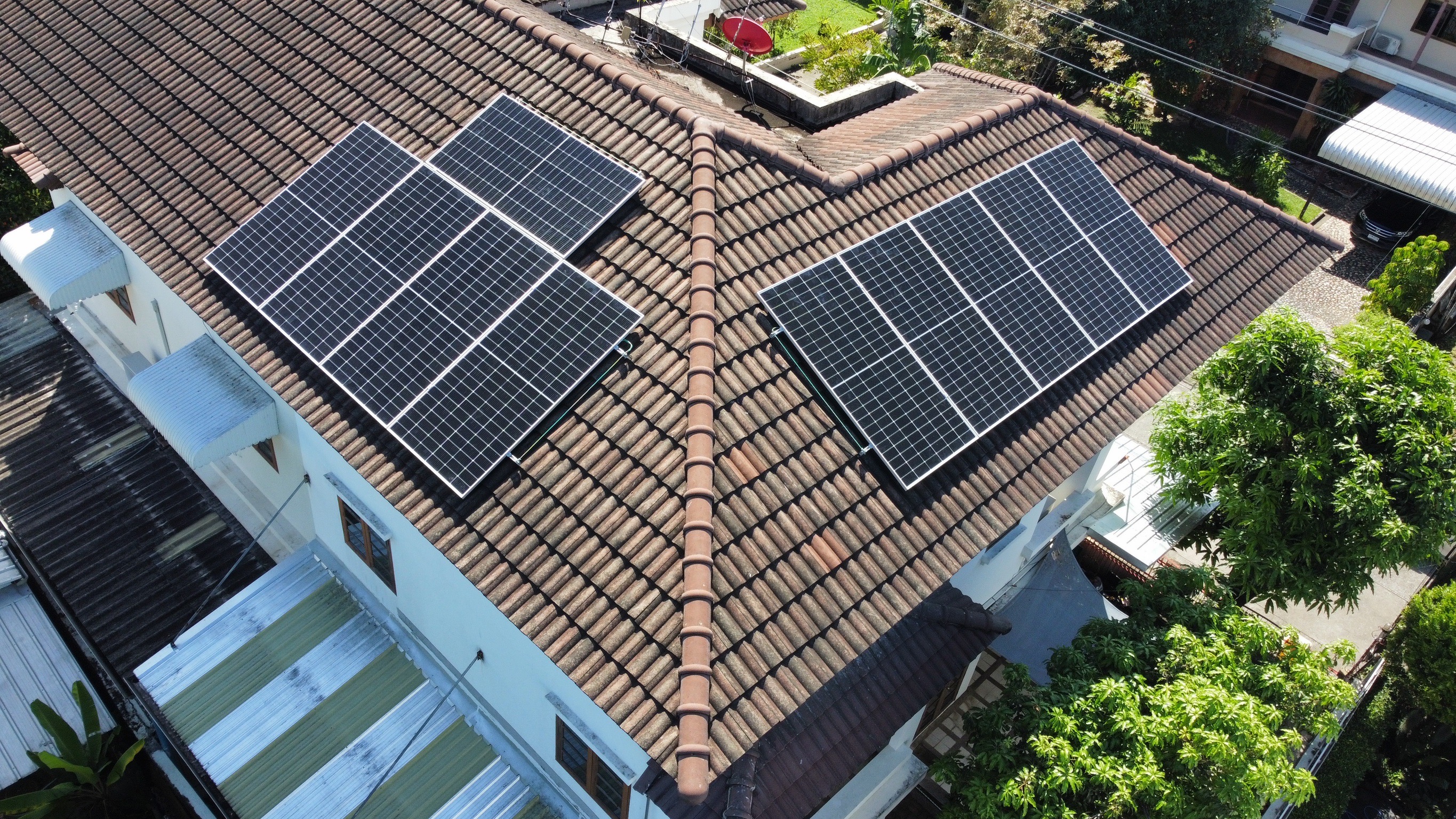
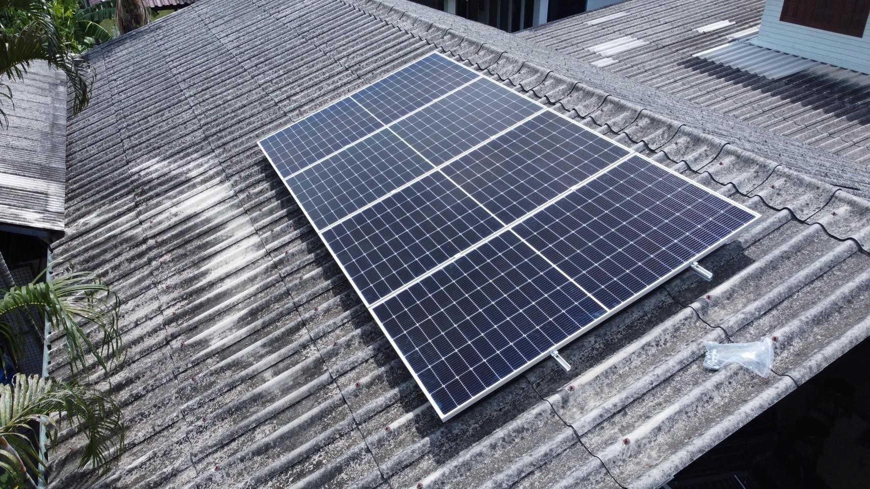
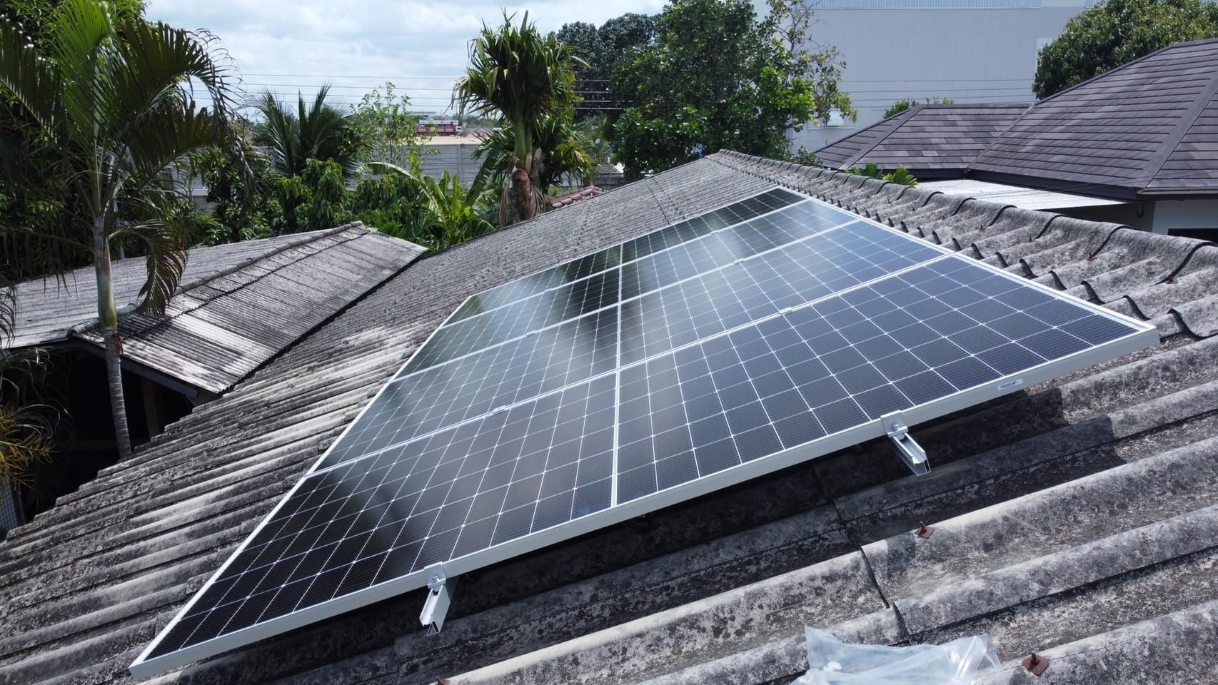
Module Mounting Structures (MMS)
Module Mounting Structures (MMS) are used to secure the PV modules in particular orientation to collect maximum sunlight. MMS are designed keeping several structural considerations such as:
-
Load (weight) of the PV system Load bearing capacity of the terrace, rooftop or the structure on which the PV system is mounted;
-
Typical and maximum wind loads at that particular location, also factoring the height of the installation;
-
Seismic zone safety factors;
-
Other considerations such as saline or corrosive environments
Most of the physical considerations are governed by Indian Standards. PV modules are often mounted at a tilt angle lower than the optimum angle for maximum energy generation. Lower tilt angles reduce the wind loads encountered by the PV system, resulting into a lighter MMS and also avoid the need to puncture a terrace, which may cause water seepage problems in the future. The mounting of PV modules should be optimized from a techno-commercial standpoint rather than just a technical performance standpoint.
Lightning arrestors
While it is desired to protect all PV systems from lightning, Lightning Arrestors may not be mandated for PV systems with capacities less than 10 kW. It is highly recommended for PV systems to have dedicated lightning arrestors rather than depending on foreign rods and structures at greater heights that might exist at the time of installation.
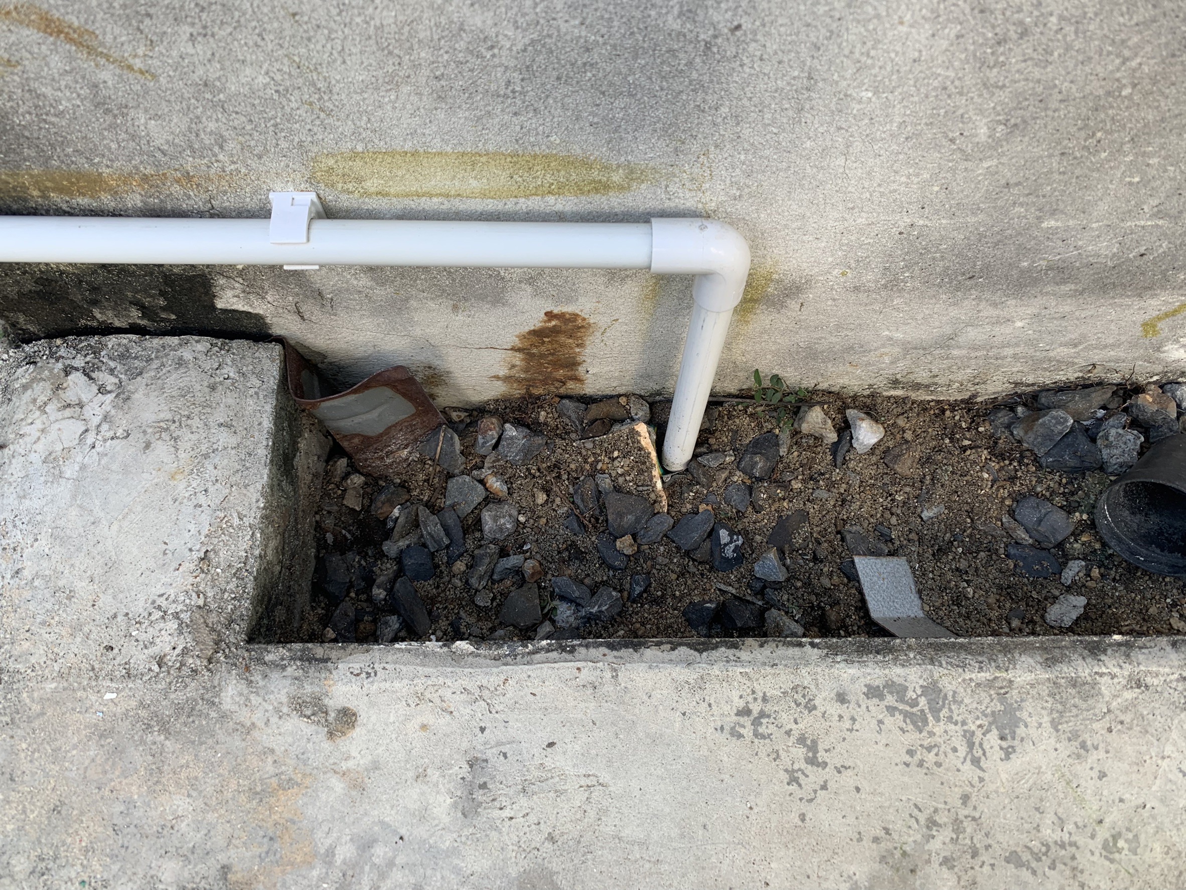
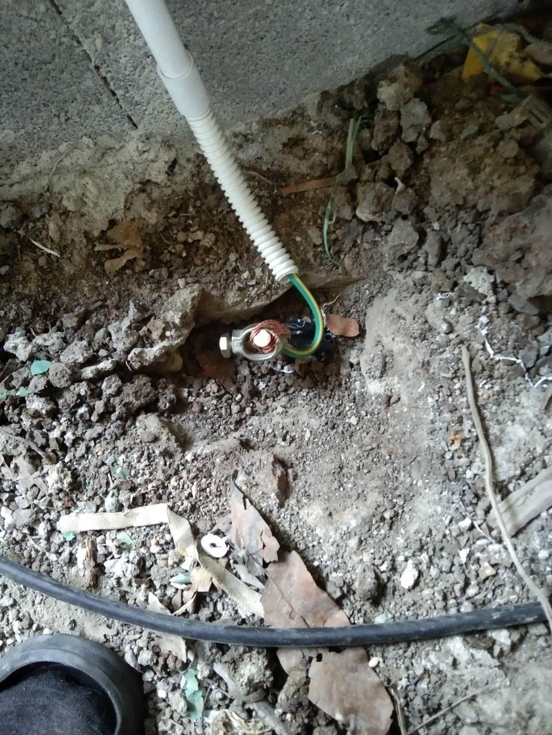
Earth Pits
Earth Pits used in solar PV systems are the same as conventional earth pits used for electrical installations and also follow the same standards. Each earthing system should have two earth pits, whether at the same end of the earthing system or each at the opposite end of the earthing system. This way, the risks from failure of the earthing system can be reduced and a lower earth resistance can be achieved.
Important Documentations
Documentation plays a significant role in understanding system components (model no, warranty, user manual, contact details, safety etc.). In RTPV systems there is no qualified person always available on site therefore, access to information especially useful during O&M. For instance, if the inverter needs to be replaced, one requires the warranty information, model number, datasheets etc. All information is available at one place, in case of an emergency the customer should have an easily accessible ready reference that gives all information about the system.
-
System Documentation
-
Component Documentation
-
Maintenance Documentation
System documentation
It covers all the documents that gives the basic overview of the rooftop solar PV system.
System description diagram
-
It gives the basic overview of understanding the basic system framework.
Equipment layout diagram/ Interconnection
-
Indicates the physical layouts including dimensions of the rooftop/ terrace as well as location of each equipment such as PV modules, inverters, DC and AC junction boxes, transformers (if applicable), etc. with clear identification and labeling of each equipment. This diagram covers the physical aspects of the installation.
-
It much be properly labeled so that the location of any string or module can be easily identified.
-
It is useful if any engineer or technician arrives for maintenance or troubleshooting.
Wire and earthing layout diagram
-
It appears similar to the equipment layout diagram, but indicates the electrical interconnections including PV modules, junction boxes, inverters, transformers (if applicable), Disconnector and various equipment, up to the interconnection or meter. In addition, this drawing also indicates the earthing interconnection scheme for various DC and AC equipment and lightning arrestor, while also clearly showing the location of the earth pits.
-
It is useful if any engineer or technician arrives for maintenance or troubleshooting.
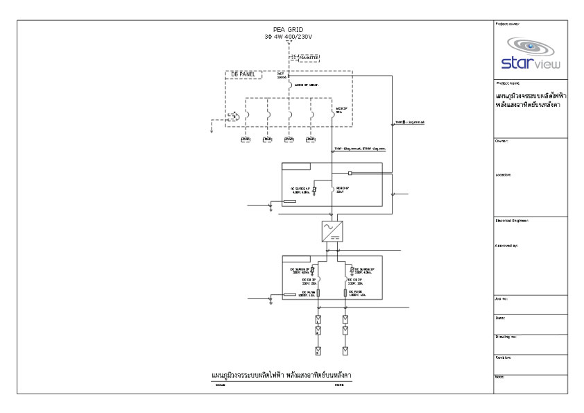
Single Line Diagram (SLD)
-
Indicates the electrical configuration of the PV system with key specifications of various components.
-
It is useful if any engineer or technician arrives for maintenance or troubleshooting.
Generation estimation report
-
Based on historical meteorological data and expected plant losses and performance parameters. Such reports can be developed manually, or using software such as PVsyst or PVSOL.
Component documentation
It covers all the documents which gives details of all components. It is very essential to get a replacement when a product malfunctions.
Component Datasheets
-
Containing datasheets of the PV modules, inverters, transformers (if applicable), DC and AC junction boxes, DC and AC cables, DC cable connectors, earthing cable, lightning arrestor, surge protection devices, Disconnector/ isolators, earth pit, monitoring system (if applicable) and energy meter
-
Datasheets will provide all the details of your product.
-
It is useful if any engineer or technician arrives for maintenance or troubleshooting.
Warranty Certificates
-
Containing warranty certificates of the PV modules, inverters, transformers (if applicable), lightning arrestor (if applicable), etc. by the Original Equipment Manufacturer (OEM).
-
It is very essential to get a replacement when a product malfunctions.
Other Certificates
-
IEC and other certificates for PV modules & Inverters
-
Containing test certificates of PV Modules so that the quality of each individual module is maintained.
-
Essential for safety purpose also.
Invoices of all products
-
Contains bills of all the products purchased
-
It is very essential to get a replacement when a product malfunctions.
Maintenance documentation
It covers all the documents which gives details of the service provider. It is very essential to get a service/replacement when a product malfunctions.
Service documentation
-
Invoice of O&M Service provider
-
Service contract must include: At what intervals the scheduled maintenance will be performed? What kind of services will be included in the maintenance contract? What will be the response time when there is service outage? What sort of system problem will incur the additional cost for the customer?
-
It is very essential to ensure the right level of service is received.
Contact Information
-
Various stake holders such as installer, project developer, EPC contractor, designer, lending agency etc.
-
O&M Service provider
Maintenance
Methods and Techniques for Cleaning PV Modules
Wet Cleaning
In this method of cleaning, water is used to eliminate dirt from the surface of the solar PV module. The cleaning process can either be manual or automated. Manual cleaning is done by using a soft cloth, brush, detergent (non-abrasive) and clean water.
Water Quality
-
Preferable quality for cleaning the modules is de-ionized water. If de-ionized water is not available, rainwater or tap water can be used. Water from a domestic reverse osmosis (RO) plant may be used.
-
The water must be free from sand and physical contaminants that could damage the module surface.
-
Tap water must be of low mineral content with total hardness not more than 200 ppm.
Water pressure
-
Use of high pressure pipes for cleaning may exert excess pressure and damage the modules.
-
Water pressure should not exceed 35 bar at the nozzle.
Water temperature
-
The temperature of water used for cleaning should be same as the ambient temperature at the time of cleaning.
-
Cleaning should be carried out when the modules are cool, in order to avoid thermal shock which can potentially cause cracks on the modules.
Stubborn marks
-
To remove dogged dirt such as grit, birds dropping, dead insects, tar etc., use a soft sponge, fiber cloth or non-abrasive brush.
-
Rinse the module immediately with plenty of water.
Drying
-
Modules should be dried after rinsing using a soft sponge or rubber wiper with a plastic frame on an extension pole.
-
Wipe the module surface from top to bottom to remove any residual water from the module.
Cleaning agent
-
A mild, non-abrasive, non-caustic detergent with de-ionized water may be used.
-
Abrasive cleaners or de-greasers should not be used.
-
Acid or alkali detergent must not be used.
NOTE
Before Cleaning
-
Do not clean damaged panels. This can result in an electric shock. Thoroughly inspect the panels for any crack, damage, and loose connections.
-
Cleaning Time: Low light conditions when production is lowest (Before 7:30 A.M. and after 6:00 P.M.) The best time to clean modules is from dusk to dawn when the plant is not in operation and risk of electric shock hazard is minimum.
During Cleaning
-
Ensure water used is free from dirt and physical contaminants. (De-ionized water is preferable). Water with mineral content more than 200 ppm should NOT be used. Cleaning agent must be mild, non-caustic and non-abrasive detergent may be used
-
Do not brush or clean on the reverse side of the modules to avoid damage to the lead wires or the junction box.
-
For removing stubborn marks of bird droppings, insects, dirt etc. make use of a soft sponge, fiber cloth or non-abrasive brush.
-
Do not sit, stand or step on the modules for cleaning.
-
Do not use a metal brush to clean solar panel surface.
After Cleaning
-
Check for any dirt accumulation at the edges of modules as figure below.
-
Do not use corrosive chemicals or steam to speed up cleaning.
Dry or Brush Cleaning
If excessive soiling is present, then a brush, sponge or a cloth may be used. This could however lead to scratches on the module and must therefore be performed cautiously. Dirt must not be rubbed vigorously or scraped, which can result in scratches on the surface of the PV module. The obvious advantage is that dry cleaning can save water requirements.
NOTE
Rainwater
Rainwater falling on panels can be saved in a tank and then used for cleaning. This will minimize the cost of cleaning PV modules. A filter must be used to clean the stored water as the rainwater contains sand and other contaminating agents that may affect the PV modules.
Safety
General Safety
-
The access and exit arrangements should be safe and clear of obstacles.
-
Communication arrangements should be safe and clear of obstacles.
-
Maintain a first aid kit to mitigate accidents involving personnel or any other person who may be in the vicinity.
-
Keep tools sharp and clean.
-
Don’t hold the switch button while carrying a plugged-in tool.
-
Consider what you wear – loose clothing and jewelry can get caught in moving parts.
-
Disconnect tools when not in use, before servicing and cleaning, and when changing accessories.
-
Keep away people who are not involved with the work.
-
Make use of an insulated tools kit.
-
Since the rooftop is located outdoors, adequate precaution should be taken to avoid sunburns, exhaustion, and de-hydration.
-
Use sunscreen, use a hat if necessary, wear light colored clothes and keep drinking a lot of water.
-
Always read the site safety notice and act accordingly.
Specific Safety
-
Grid connected PV systems are expected to have a lifetime of decades with maintenance/ modifications likely at some point over the period. It makes it essential for the PV system to be protected.
-
Switch enclosures must also be labeled with “Danger - contains live parts during daylight”.
-
Ensure that the solar isolation switch is off and the mains has been isolated. This may be located either on the main fuse board or near the inverter. The solar panels and the wiring to the inverter/fuse board will still remain live.
-
If the control equipment or cabling becomes complicated, or closer to the fire. Monitor fire spread, and contact branch operators.
-
As with any electricity generating equipment, do not approach or make contact with any parts that are not considered ‘dead & earthed’, and arrange for the attendance of the electricity authority for advice and guidance.
-
Before operating the Inverter, ensure that the power cable and wall outlet have been grounded properly.
-
Repairs or testing under power must only be performed by qualified technicians who are familiar with and qualified to work with the Inverter.
Types of Hazards
-
Physical Hazards
-
Electrical Hazards
-
Chemical Hazards
Physical Hazards (Personal Protections)
Safety helmet
Protection of the head is very important because injuries to the head are very serious. A hard hat is a type of helmet predominantly used in workplace environments such as industrial or construction sites to protect the head from injury due to falling objects, debris, rain, and electric shock.
Suspension bands inside the helmet divide the helmet’s weight and the force of any impact over the top of the head. It provides space of approximately 30 mm (1.2 inch) between the helmet’s shell and the wearer’s head, so that if an object strikes the shell, the impact is sensed less directly on the skull.
Safety Glasses
-
Safety glasses are forms of protective eye wear that usually enclose or protect the area surrounding the eye in order to prevent particulates, chemicals from striking the eyes. Goggles are frequently worn when using power tools such as drills or chainsaws to prevent flying particles from damaging the eyes.
-
Sunglasses or regular glasses are not appropriate safety glasses.
-
For employees who use spectacles they must use goggles that can fit comfortably over corrective eyeglasses without disturbing their alignment.
Hand Gloves
-
Tools and machines with a sharp edge can cut your hands. For electrical works, rubber insulating gloves are among the most important articles of personal protection. To be effective, electrical safety gloves must include high dielectric and physical strength, along with flexibility and durability.
-
Two kinds of gloves are commonly used: PVC Gloves and Cotton Gloves.
Safety belts/ Body harness
-
Personal protection against falling from high structures
-
Enables comfortable working position with protection against imbalance and slipping.
-
Climbing to a location that is inaccessible from inside the building/household using an anchorage and suspension line.
-
PVC coated jackets provide protection from extreme or harsh weather conditions, injury from sharp tools and chemicals or fluids that should not come in contact with the body.
Safety Shoes
-
Safety shoes protects you from electrical shocks & burns, extreme heat, extreme moisture (can lead to fungal infections) and slipping (oil, water, soaps, wax, and other chemicals can cause you to slip and fall.)
-
At work, heavy objects can fall on your feet. If you work around sharp objects, you can step on something sharp and injure your foot.
-
3-4 active modules produce a dangerous voltage for a person touching exposed wires. Therefore, safety precautions need to be employed.
-
If the inverter is disconnected from the modules or from the output AC side, high voltages remain may continue to exist.
Electrical Hazards
Risk to installers and maintenance personnel
-
Specific electrical hazards are related to maintenance activities on the electrical parts of the PV plant. Specifically, during array connection during installation and replacement of PV panels there are potential electrocution hazards.
-
The most common accidents are electrical shocks and burns, contraction of muscles and other severe injuries. These injuries can take place at anytime if proper safety measures are not followed. It is difficult to estimate the severity of electrical injury because if the human body is exposed to a voltage, it acts like a resistor and allows the current to pass.
Risk to firefighters
-
False assumptions can lead to disasters. Firefighters commonly cut off electric grid supply to burning buildings as a precaution procedure before extinguishing the fire. They assume, that once the grid has been disconnected there is no risk of electrocution, allowing the spray of water.
-
Unfortunately, this assumption is not true in case of a RTPV system. PV systems are always energized when exposed to sunlight. Traditionally, rooftop PV systems operate at up to 1,000 V DC (modern systems can even go as high as 1,500 V). Opening disconnects interrupts current flow. Hazardous voltages remain even with disconnects open.
-
Always check the voltage between any conductor and any other wires, and to ground.
-
Always wear gloves and avoid touching conductive parts (e.g., battery terminals, metal and mounting frames) with bare hands.
-
Electric sparks and loose connection can lead to a fire. Take proper preventive measures:
-
Use insulated tools (e.g., spanners)
-
Ensure that the battery terminals are covered
-
Check contacts and voltage drop
-
Tighten up all screws
-
Check cable and terminal block periodically
-
Chemical Hazards
Hydrogen is produced when a lead/acid battery is charged. Therefore, install battery in well-ventilated area and keep flames and equipment that create spark away from the battery. A multipurpose extinguisher is a good choice. Use of CO2 operated fire extinguisher should be avoided because they extinguish fire by removing oxygen. Fire Extinguishers category:
-
Class A: For fires involving conventional combustible materials such as paper and wood.
-
Class B: For fires involving flammable or combustible liquids or gases, greases and similar materials.
-
Class C: For fires involving energized electrical equipment.
-
Class K: For fires involving combustible metals